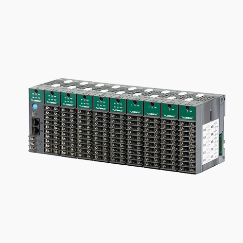
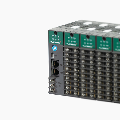
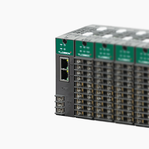
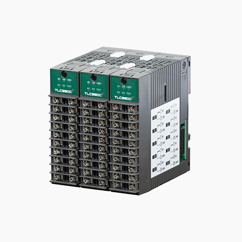
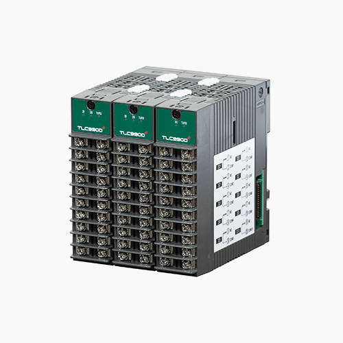
1280チャンネルモジュール型温度コントローラー
TLC990e SERIES
It is a multi-channel(1280channel) temperature programmable controller, supports high-definition TFT-LCD touch screen, SD card and multi-channel control function.
-
Selection of channel for system
Control of 4 channel ~ 1280 channel and selection of monitoring
-
High accuracy
Precision control with 18bit A/D convertor
±0.1% of full scale ±1 digit
-
Various control modes
Heating/cooling and cascade control according to equipment characteristics. (optional)
-

Individual RUN/STOP without trigger
Prevent malfunction by communication delay case of multiful alrams.
-

Self testing software
TLC automatically tests installation state
-

Selectable data communication
It prevents from decreasing speed by unnecessary large data
-

Heater burn-out alarm(12A, 50A, 100A)
Supporting whole control output(1,280 channel)
-

Users’ communication
User can change whole TLC data at the PLC
-

40 Digital outputs/32 DIgital inputs
The various alarm output is possible The individual RUN/STOP is possible using external inputs
-

Automatically connecting recognition
Recognizing devices without initialization
-

Power saving mode
By automatic control of MV, the system is economical and safe
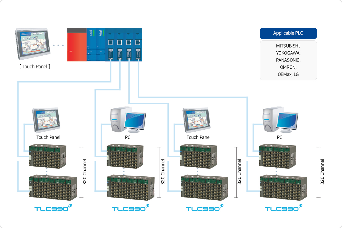
Connect to Serial port
Connect each Max. 320 channel to one PLC module.
So, Max, 1280 channel connectable
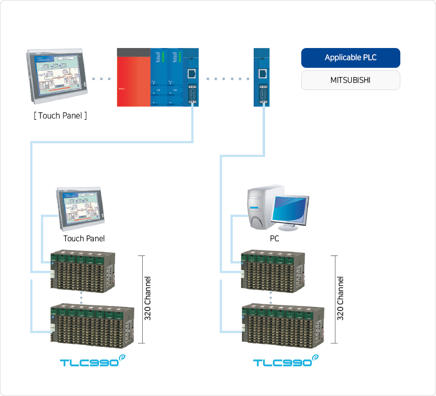
Connect to Ethernet port
Connect each Max. 320 channel to one PLC module.
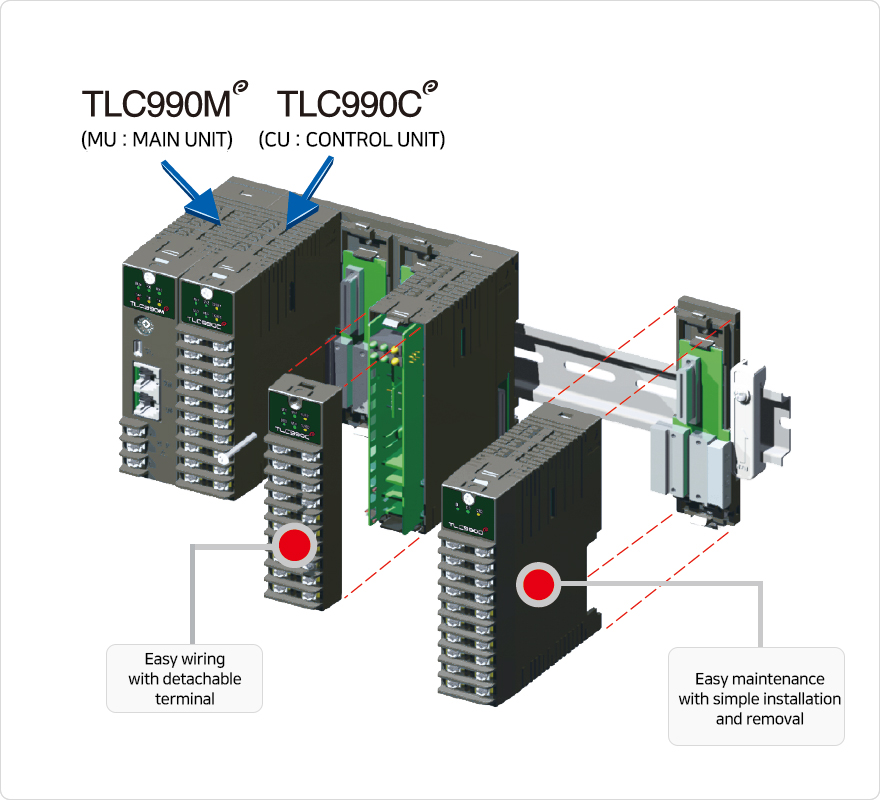
Terminal & Product installation, removal
Improved maintenance and repair with simple installation and removal
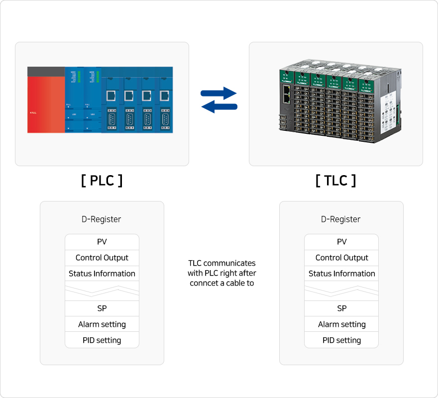
TLC can communicate any PLC without extra softwares
Use PLC user zone(area)
Active practice TLC parameters save automatically in PLC user zone
| Group | TLC990E | |||
|---|---|---|---|---|
| Display method | No indication : Parameter setting and monitoring using external connected devices (PC, PLC, GP, etc.) and serial communications(PC only program) |
|||
| Control mode | Normal control, Heating· Cooling control, Cascade normal control, Cascade Heating· Cooling control |
|||
| Analog input | Number of channel | 4 channel/CU(Universal input) |
||
| Max. number of control channel | 1280 channel/320MU(MU 1EA + CU 5EA) |
|||
| Input type | TC |
K, J, E, T, R, B, S, L, N, U, W, PL, C |
||
RTD |
PtA, PtB, PtC, JPtA, JPtB, JPtC |
|||
DCV |
0~10mV DC, -10~10mV DC, -10~20mV DC, 0~100mV DC, -50~100mV DC, 0~1V DC, -1~1V DC, 0~5V DC, 1~5V DC, -5~5V DC, 0.4~2V DC, 0~10V DC, -5~10V DC (4~20mA, 0~20mA, External resistance 250Ω, 500Ω Attach) |
|||
| Sampling time | 250ms/Channel |
|||
| Input accuracy | ±0.1% of full scale ±1 digit(A/D 18 bits) |
|||
| Analog output | Output specification | SSR |
ON voltage : 15VDC(Load resistance : Min. 600Ω/Pulse width : Min. 5ms) |
|
SCR |
4~20mA DC, 0~20mA DC, 0~5V DC, 1~5V DC, 0~10V DC, 0~100mV DC (Load resistance : Max.550Ω) |
|||
Relay |
- |
|||
| Output accuracy | ±0.3%(D/A 14bits) |
|||
| Digital input/ Digital output |
Number of input/Digita |
DI 32points & DO 20points, DO 40points Max.
|
||
| Contact point quantity of input |
Max. 12V DC, 10mA
|
|||
| Contact point quantity of output |
Normal open(Max. 30V DC/1A, 250V AC/1A)
|
|||
| Heater break alarm (HBA) |
Type | 12A, 50A, 100A |
||
| CT sensor/Accuracy | 800:1/±3% of full scale ±1 digit |
|||
| Alarm | 2points/Channel(21 Type) |
|||
| Communication | Interface | RS232C, RS422A, RS485 (Communication speed : 9600, 19200, 38400, 115200 bps) |
||
ETHERNET(10BASE-T or 100BASE-TX) |
||||
| Protocol | PC-Link, PC-Link(Checksum), Modbus(ASCII, RTU), Modbus TCP |
|||
| Electric source | Power | 24V DC |
||
| Power consumption | 6VA Max.(MU 1EA+CU 1EA) |
|||
25VA Max.(MU 1EA+CU 5EA) |
||||
35VA Max.(MU 1EA+CU 5EA+DO 4EA) |
||||
| Operating environment | 10~50˚C, 20~90% RH |
|||
| Weight | MU : 116g, CU : 182.5g |
|||
DIO : 205g, DO : 190g |
||||
Model code(TLC990E)
| Model | Additional code | Contents | ||
|---|---|---|---|---|
| TLC990ME | - | □ | □ | |
| Communication COM1 & COM2 |
8 | RS485 |
||
| 2 | RS422A |
|||
| Ethernet port |
C | Ethernet |
||
Communication COM3 |
3 | RS232C |
||
| 8 | RS485 |
|||
Ethernet port |
E | Ethernet |
||
| Model | Additional code | Contents | ||||||||||||||||
|---|---|---|---|---|---|---|---|---|---|---|---|---|---|---|---|---|---|---|
| TLC990CE | - | □ | □ | - | □□□ | □□□ | - | □ | □ | □ | □ | - | □ | □ | - | □ | □ | Channel1,2 model code |
| - | □ | □ | - | □□□ | □□□ | - | □ | □ | □ | □ | - | □ | □ | - | □ | □ | Channel3,4 model code | |
| Channel1/2, 3/4 control method |
1 | 1Channel normal control |
||||||||||||||||
| 2 | 2Channel normal control |
|||||||||||||||||
| H | Heating·Cooling control |
|||||||||||||||||
| C | Cascade control |
|||||||||||||||||
| D | Cascade control Heating·Cooling control |
|||||||||||||||||
| Channel1/2, 3/4 sampling time |
1 | 100ms/Channel |
||||||||||||||||
| 2 | 250ms/Channel |
|||||||||||||||||
| Channel1,3 input type |
K01 | K type(-200~1370℃) |
||||||||||||||||
| ··· | See manual input table(T/C, RTD, DCV) |
|||||||||||||||||
| Channel2,4 input type |
K01 | K type(-200~1370℃) |
||||||||||||||||
| ··· | See manual input table(T/C, RTD, DCV) |
|||||||||||||||||
| Channel1,3 output type |
S | SSR(0~15V DC) |
||||||||||||||||
| C | SCR(4~20mA DC) |
|||||||||||||||||
| 1 | 0~20mA DC |
|||||||||||||||||
| 2 | 0~5V DC |
|||||||||||||||||
| 3 | 1~5V DC |
|||||||||||||||||
| 4 | 0~10V DC |
|||||||||||||||||
| 5 | 0~100mV DC |
|||||||||||||||||
| Channel1,3 control type |
A | ON/OFF control(reverse) |
||||||||||||||||
| C | ON/OFF control(forward) |
|||||||||||||||||
| R | PID control(reverse) |
|||||||||||||||||
| F | PID control(forward) |
|||||||||||||||||
| Channel2,4 output type |
S | SSR(0~15V DC) |
||||||||||||||||
| C | SCR(4~20mA DC) |
|||||||||||||||||
| 1 | 0~20mA DC |
|||||||||||||||||
| 2 | 0~5V DC |
|||||||||||||||||
| 3 | 1~5V DC |
|||||||||||||||||
| 4 | 0~10V DC |
|||||||||||||||||
| 5 | 0~100mV DC |
|||||||||||||||||
| Channel2,4 control type |
A | ON/OFF control(reverse) |
||||||||||||||||
| C | ON/OFF control(forward) |
|||||||||||||||||
| R | PID control(reverse) |
|||||||||||||||||
| F | PID control(forward) |
|||||||||||||||||
| Channel1,3 heater break alarm |
N | None |
||||||||||||||||
| A | HBA(50A) |
|||||||||||||||||
| B | HBA(100A) |
|||||||||||||||||
| C | HBA(12A) |
|||||||||||||||||
| Channel2,4 heater break alarm |
N | None |
||||||||||||||||
| A | HBA(50A) |
|||||||||||||||||
| B | HBA(100A) |
|||||||||||||||||
| C | HBA(12A) |
|||||||||||||||||
| Channel1/2, 3/4 alarm1 type |
01 | PV upper limit (AH.F) |
||||||||||||||||
| ··· | See manual alarm table (21type) |
|||||||||||||||||
| Channel1/2, 3/4 alarm2 type |
01 | PV upper limit (AH.F) |
||||||||||||||||
| ··· | See manual alarm table (21type) |
|||||||||||||||||
| Model | Additional code | Contents | |
|---|---|---|---|
| TLC990DE | - | □ | |
| DIO & DO |
A | DO 5points(Independent COM) DI 8points |
|
| B | DO 10points(Independent COM) |
||
| 1 | Manual | TLC990E Instruction manual | |
| TLC990E-CE Ethernet manual | |||
| TLC990 Instruction manual | |||
| TLC880 Instruction manual | |||
| TLC990E Software manual | |||
| TLC990 Software manual | |||
| TLC880 Software manual | |||
| 2 | Catalogue | Catalogue | |
| 3 | Dimension | Dimension | |
| 4 | Software | TLC990E Software | |
| TLC990 Software | |||
| TLC880 Software |
