7チャンネルタッチタイププログラマブル温度コントローラー
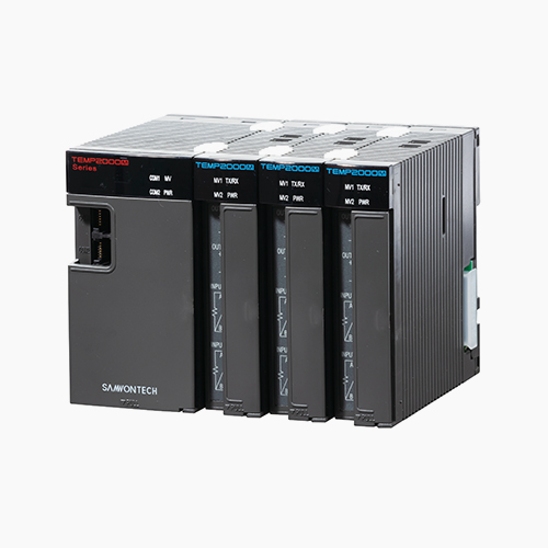
TEMP2000M SERIES
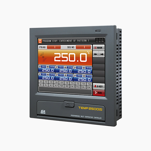
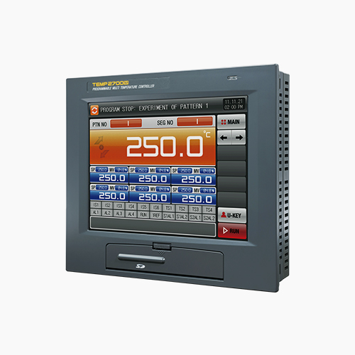
It is a multi-channel programmable controller which supports high-definition TFT-LCD touch screen, SD card and multi-channel control function
-
Selection of channel for system
Control of 3 channel / 5 channel /7 channel and selection of recording
-
High accuracy
Precision control with 18bit A/D convertor
±0.1% of full scale ±1 digit
-
Control PID of a variety
Temperature control PID group(5 Zone PID + 1 Deviation PID or 6 Seg PID)Zone, Deviation PID etc. Various PID offer
-
Various unit displays
Available 12 kinds of various unit to display under DCV sensor (˚C, ˚F, EDIT, %, ㎩, ㎪, %RH, ㎷, V, Ω, mmHg, kgf)
-

Diverse control method in sub channel
Available for independent control and sync controlAvailable for setting the individual operation calibration datain sub channel during sync operation
-

Supporting the heater short (12A, 50A and 100A)
Display by measuring the current flowing in the heater andavailable for short alarm output Use of 800:1 CT
-

Total 6 channel digital recording
Real time monitoring and data saving for the present data of main channel,setting data and the present data of output quantity and sub channel
-

Multi-language system
Supporting of various languages of korean, english, Chinese, Japanese and russian
-

SD memory card support
Data storing into the SD memory card and available for up/down of the set parameter
-

Powerful communication
Basic include RS232C/485 serial communication (Communication speed 115,200bps) Ethernet support option
-

Operation time management
Display of the operation starting time, estimated termination time and operation time up to now
-

Free PC software
Free PC multi-monitoring software for communication and SD viewer for data management of SD data
Supporting SD memory card
-

Selectable Initial screen
User can choose appropriate initial screen
-
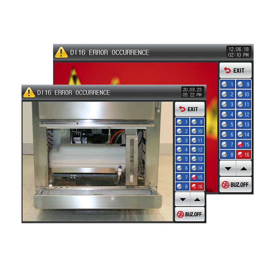
Editable Error Screen
Self-designed picture can be used
-

Electronic Album
Company and product profiles can be displayed
-
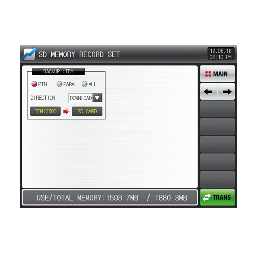
Data recording with SD card
Data acquisition of process value.
Up/Download parameter and pattern data.
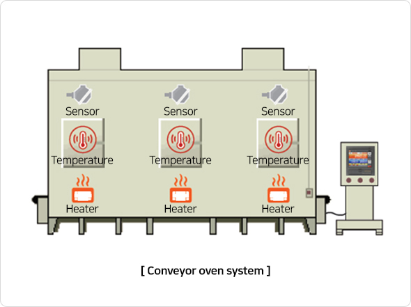
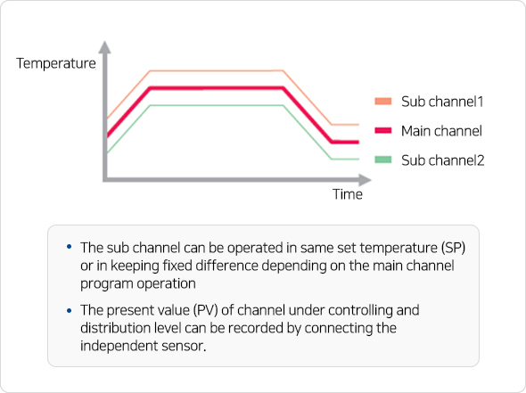
Sync Control
It is an operating method of synchronizing the operation state and setting value (SP) of main channel with sub channel.
Application system: Electric furnace, continuous furnace and ripple lower
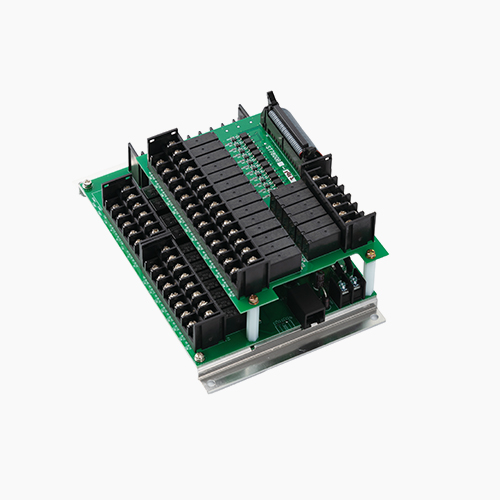
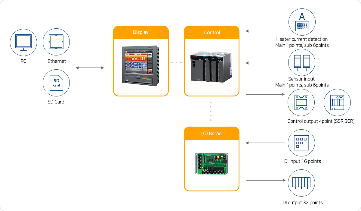
Separated hardware
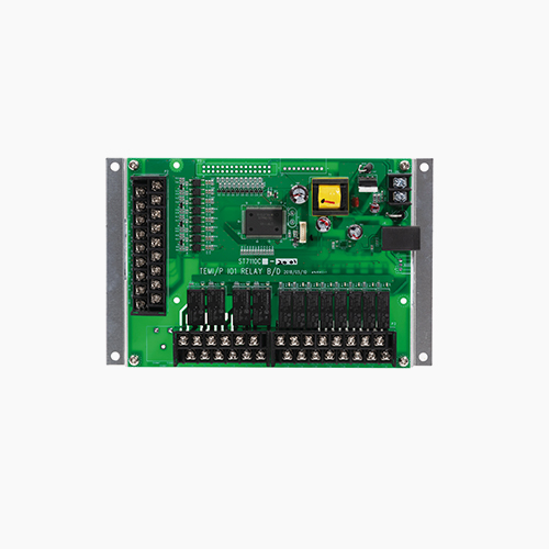
Configuration separated by display, control, and input / output board
Available to mount panel mount and VESA mount
Various system configurations and work ability
| Group | Item | TEMP2500M | TEMP2700M | TEMP2000M |
|---|---|---|---|---|
| Screen | Display | 5.7* TFT-LCD |
7.5* TFT-LCD |
- |
| Resolution | 640(W) x 480(H) |
- | ||
| Language | Korean, English, Chinese/Korean, English, Japanese |
- | ||
| User screen | Change of initial screen, Electronic album function |
- | ||
| Mount type | Panel mount, VESA mount(MIS-D 75) |
- | ||
| Operation screen | Basic screen, available for making drawing which meets customer needs(Option) |
- | ||
| Control channel | Main channel | 1 channel |
- | |
| Sub channel | - |
Selection of 2/4/6 channel |
||
| Analog input | Input quantity | 1point(Universal input) |
2/4/6point(Universal input) |
|
| Sensor type | TC |
K, J, E, T, R, B, S, L, N, U, W, Platinel Ⅱ, C |
||
RTD |
Pt100(IEC), Jpt100(JIS), 1/100 Displayable |
|||
DCV |
0.4~2V, 1~5V, 0~10V, -10~20mV, 0~100mV (4~20mV, 0~20mV, External resistance 250Ω, 500Ω Attach) Scale : -1999 ~ 30000 |
|||
| Sampling period | 250ms/Channel |
|||
| Input accuracy | ±0.1% of full scale ±1 digit |
|||
| Analog output | Output specification (Max. 2point) |
Voltage output(SSR) 2points |
ON voltage : 15V DC (Load resistance:Min 600Ω/pulse width: Min 5ms) |
1point/Channel |
Current output(SSR) 2points |
4~20mA DC(Load resistance: Max. 600Ω) |
|||
| Output type | Control output/Transmission output(PV, SP)/Auxiliary output |
Control output |
||
| Digital input | Contact point specification |
Basic 16points(Contact point capacity : Max. 12V DC, 10mA) Selection of operation for A or B point
|
||
| Contact point function |
Run/Stop/Hold/Step, selectable run patterns, set DI detect delay time, select DI error monitor(text or picture)
|
|||
| Digital output | Contact point quantity | Basic 12points(A contact point relay 8points + C contact point relay 4points), Option(A contact point relay 20points) addition function |
||
| Contact point specification | Normal open(Max. 30V DC/1A, 250V AC/1A), Normal close(Max. 30V DC/1A, 250V AC/1A) |
|||
| Signal type | Inner signal(8points) On/Off signal(7points) Logical signal(3points) Error signal(1point) User signal(1point) |
Alarm signal (2points/channel) Heat break alarm signal (1point/Channel) |
||
Time signal(8points) DI signal(16points) Sensor open signal(1point) Hba signal(1point) Ref signal(2points) |
||||
Alarm signal(4points) Manual signal(16points) Wait signal(1point) Up· Soak· Down signal(each 1point) |
||||
Seg alarm signal(4points) Run signal(1point) Fix timer signal(1point) Fix· Programmable end signal(each 1point) |
||||
| Heater current detection |
Type | 12A, 50A, 100A |
||
| CT sensor/Accuracy | 800:1/±3% of full scale ±1 digit |
|||
| Program | Pattern/Segment | 40 pattern/600 segments |
- | |
| Segment time | Max. 999hours 59minutes 59seconds |
- | ||
| Function | Up/Down slope rate, Wait, Operating start code, Pattern name, Power stop mode, PT end mode |
- | ||
| Repetition | Pattern/Segment repeat operation |
- | ||
| PID control | PID groups | 6 PID groups(5 Zone PID groups + 1 Deviation PID group or 6 Seg PID groups) |
1 PID group/channel |
|
| Data back-up | Storage media | SD/SDHC card(FAT32 format) |
||
| Logging function | Program pattern/Parameter set data backup and recovery, available for sectional saving max. 6points out of main channel and sub channel PV |
|||
| Communication | Interface | Basic : Flexible to change between RS485/RS232C by DIP switch, Max. 31 nodes. Max. 115,200 bps, |
||
Option : Ethernet(TCP/IP) *In case of selection of ethernet, RS232C/485 is not available |
||||
| Power | Rated voltage | 24V DC 22VA Max. |
||
| Lithium battery | For setup data retention(CR2032) |
|||
Model code (TEMP2000M)
| Model | Additional code | Contents | ||||||||||||||
|---|---|---|---|---|---|---|---|---|---|---|---|---|---|---|---|---|
| TEMP2 | □ | 0 | 0 | M | - | 0 | □ | / | □ | / | □ | / | □ | / | □ | |
| Size |
5 | 5.7inch (IP65 certification) |
||||||||||||||
| 7 | 7.5inch |
|||||||||||||||
I/O board |
0 | I/O1 (DO12points, DI16points) |
||||||||||||||
| 1 | I/O1, 2 (DO32points, DI16points) |
|||||||||||||||
SD card |
SD | SD card(ST'D) |
||||||||||||||
communication |
RS | RS232C/485(ST'D) |
||||||||||||||
| CE | Ethernet(TCP/IP) |
|||||||||||||||
Heater break alarm |
N | None |
||||||||||||||
| A | 50A |
|||||||||||||||
| B | 100A |
|||||||||||||||
| C | 12A |
|||||||||||||||
Sub channel |
CH2 | 2channels |
||||||||||||||
| CH4 | 4channels |
|||||||||||||||
| CH6 | 6channels |
|||||||||||||||
Model code (TEMP2000M Sub Channel)
| Model | Additional code | Contents | |||||||
|---|---|---|---|---|---|---|---|---|---|
| TEMP2 | 0 | 0 | 0 | M | / | □ | / | □ | |
Heater break alarm(ch1) |
N | None |
|||||||
| A | 50A |
||||||||
| B | 100A |
||||||||
| C | 12A |
||||||||
Heater break alarm(ch2) |
N | None |
|||||||
| A | 50A |
||||||||
| B | 100A |
||||||||
| C | 12A |
||||||||
| 1 | Manual | Instruction manual | |
| Communication manual | |||
| SIMS Manual | |||
| PME Manual | |||
| BitEditor Manual | |||
| 2 | Catalogue | Catalogue | |
| 3 | Dimension | Dimension | |
| 4 | Software | SIMS - Integrated communication software | |
| PME - Integrated parameter editor software | |||
| BitEditor - Image editor software | |||
| 5 | Executable file | SIMS, PME Additional files |
